HOW TO USE
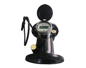
The 4G large caliber ultrasonic water meter adopts the advanced ultrasonic measurement technique to measure the water flow in pipes, and upload water meter data by 4G way.
The whole 4G meter reading system consists of wireless ultrasonic water meter, 4G modem, and monitoring management software. The management center can read and monitor water meter accumulated water consumption, instantaneous water flowrate info by 4G network directly.
The FS smart water meter upload data info through 4G to management center, such as accumulated consumption curve, real time accumulated consumption, instantaneous flow etc. Besides, the water meter also can detect the pipe pressure. It will collect the pipe pressure data to management center at fixed time. The administrator could check the data through software, if there is abnormal, the alarming message will be uploaded to management center. The management center can transmit alarming message to administrator for them check and resolve in time.
FUNCTIONS
1. Measured by ultrasonic, and separately adjusted, with high precision,
and avoid magnet attack.
2. There is no moving parts,
and no wear and tear, and maintain 100% accuracy for its lifetime.
3. The real time monitor period can be set by software, at monitor
period, the software can communicate with the terminal and read or freeze the terminal
data.
4. The data can be freeze each 15 minutes, and one message can read 96
freeze data each day, which save a lot of meter reading cost.
5. 4G is the priority, which save meter reading cost.
TECHNICAL PARAMETERS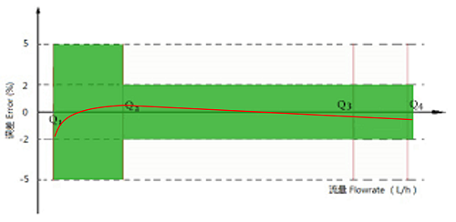
|
Caliber
|
Overload Flowrate
(Q4)
|
Permanent
Flowrate
(Q3)
|
Transitional
Flowrate
(Q2)
|
Minimum
Flowrate
(Q1)
|
|
20
|
5 m³/h
|
4 m³/h
|
0.08
m³/h
|
0.05
m³/h
|
|
25
|
7.875
m³/h
|
6.3
m³/h
|
0.126
m³/h
|
0.0788
m³/h
|
|
40
|
20
m³/h
|
16
m³/h
|
0.32
m³/h
|
0.20
m³/h
|
|
50
|
31.25
m³/h
|
25
m³/h
|
0.5
m³/h
|
0.3125
m³/h
|
|
65
|
50
m³/h
|
40
m³/h
|
0.8
m³/h
|
0.5
m³/h
|
|
80
|
78.75
m³/h
|
63
m³/h
|
1.26
m³/h
|
0.7875
m³/h
|
|
100
|
125
m³/h
|
100
m³/h
|
2 m³/h
|
1.25
m³/h
|
|
125
|
200
m³/h
|
160
m³/h
|
3.2
m³/h
|
2 m³/h
|
|
150
|
312.5
m³/h
|
250
m³/h
|
5 m³/h
|
3.125
m³/h
|
|
200
|
500
m³/h
|
400
m³/h
|
8 m³/h
|
5 m³/h
|
|
250
|
787.5
m³/h
|
630
m³/h
|
12.6
m³/h
|
7.875
m³/h
|
|
300
|
1250
m³/h
|
1000
m³/h
|
20
m³/h
|
12.5
m³/h
|
|
400
|
2000
m³/h
|
1600
m³/h
|
32
m³/h
|
20
m³/h
|
|
Maximum Allowed
Error
|
Q1≤Q<Q2 Error≤±5%;
Q2≤Q≤Q4 Error≤±2%
|
|
Minimum Display
of Flowrate
|
0.01m3 (using
status)
0.00001m3 (checking
status)
|
|
Digits of
LCD
|
8 digits
|
|
Max Accumulated
Flowrate
|
4.2×10⁹ m3(Only
final 8 numbers can be displayed when accumulated flow rate is more
than 99999999m3 )
|
|
Working Status
Indicator
|
LCD display
in turn
|
|
Working Temperature
|
0.1℃~30℃;
|
|
Pressure Resisting
|
1.6MPa
|
|
Loss
of Pressure
|
Δp25
|
|
Flow Section
Sensitivity Level
|
U10,D5
|
|
Climate & Mechanical
Environment Safety Level
|
Class
B
|
|
EMC level
|
E1
|
INSTALLATION
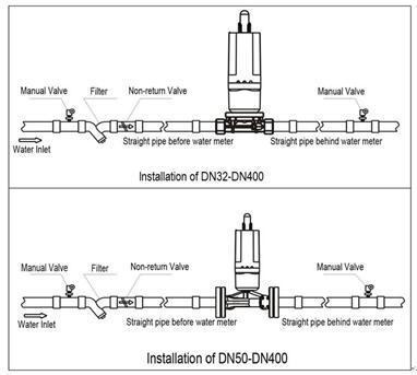
1) Installation of common type water meter:
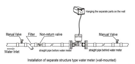
2) Installation of separate structure type water meter:
Note:
Common type water meter is recommended to install above the ground, and
separate structure type water meter adopts underground installation (mounted
close to the entrance of the well or directly install on the well cover).
3) Notice:
1. The installation of water meter should meet the installation requirement of GB/T 778.2
2. It is suggested that install a filter in front of the water meter and install valve in front of the filter, convenient for repairing and cleaning the filter.
3. Before installation, please clean the pipe firstly to avoid small stones or other sundries inside the pipe, which will cause problem for water meter.
4. During the installation,
please don’t wrench, move or knock the component inside of the pipe, to avoid
knocking against the meter body.
5. Please leave enough space for repairing, and installation according
to water flow direction on the pipe.
6. Please do not apply too
much force when connecting the water meter and pipe, to avoid damaging the
meter body and result in water leakage.
7. Please do not knock meter
shell violently or cause sharp pounding, avoid breaking the water meter.
8. When install the separate structure type water meter, the cable
between two parts is 3 meters.
DIMENSION
1) Dimension of DN32-DN40
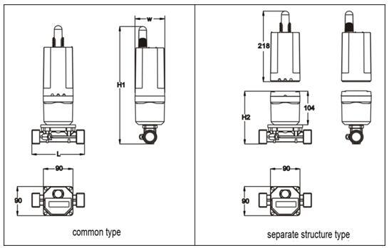
2) Dimension
of DN50~DN300
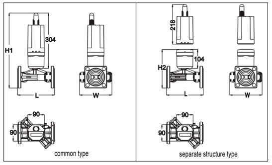
|
Caliber(mm )
|
Length
L(mm )
|
Width
(mm )
|
Height
H1(mm )
|
Height
H2(mm )
|
Connection Way
(¢E-n×¢D)
|
|
DN32
|
180
|
90
|
336
|
136
|
Screw G1-1/2B
|
|
DN40
|
200
|
90
|
349
|
149
|
Screw G2B
|
|
DN50
|
200
|
140
|
432
|
232
|
Flange¢125-4×¢18
|
|
DN65
|
200
|
160
|
454
|
254
|
Flange¢145-4×¢18
|
|
DN80
|
225
|
185
|
467
|
267
|
Flange¢160-8×¢18
|
|
DN100
|
250
|
200
|
490
|
290
|
Flange¢180-8×¢18
|
|
DN125
|
250
|
250
|
469
|
269
|
Flange¢210-8×¢18
|
|
DN150
|
300
|
285
|
499
|
299
|
Flange¢240-8×¢22
|
|
DN200
|
350
|
340
|
554
|
354
|
Flange¢295-12×¢22
|
|
DN250
|
450
|
405
|
639
|
439
|
Flange¢355-12×¢26
|
|
DN300
|
500
|
460
|
694
|
494
|
Flange¢410-12×¢26
|
MAIN TECHNIQUES
1. Totally seal design, waterproof, moisture proof, anti-attack and against broken.
2. Easy for installation, can be installed horizontally or vertically.
3. Smart water meter with remote valve control: there is no wire connection between smart water meter and valve controller, easy for installation.
 PRODUCTS