HOW TO USE
RLBFL-C is a kind of instrument used to measure and display the released heat power when the heat-carrying liquid pass through the heat exchange system.
It has two parts, which is RLBFL-C heat meter and its controller. The controller and heat meter are separated structure and communicates by wireless way. The heat meter is consisted of flow sensor, microprocessor and matched pair temperature sensor.
The microprocessor gets the flow signal through flow sensor and the signal of water temperature at the entrance and exit from the temperature measuring circuit, and then calculates exchanged heat by the heat-carrying liquid according to the standard heat calculation formula, and uploads the power to the controller at regular time. The controller will deduct the consumption and will close valve and stop heat power supply when the purchased power is used up.
The meter is designed and developed on the basis of the European Standard EN1434 and OIML-R75 International Standard, and has high performance and low energy consumption, and in line with the product standard CJ128-2007 Heat Meter issued by Ministry of Construction of China.
FUNCTIONS
1. Prepaid function
2. Alarms when voltage is low.
3. High definition and wide temperature LCD display
4. Flow rate has 8 levels and are separately adjusted, with high precision.
5. Alarms when the temperature sensor is disconnected or has a short circuit.
6. Measuring mechanism has no moving parts and no wear and tear forever. The measuring accuracy will not be influenced by usage period.
7. Optical interface, long distance communication, read meter by PDA.
8. Horizontal or vertical installment.
TECHNICAL PARAMETERS
|
Caliber(mm)
|
Common
Flowrate
Qp
|
Min
Flowrate
Qmin
|
Max
Flowrate
Qs
|
|
40
|
10
|
0.2
|
20
|
|
50
|
15
|
0.6
|
30
|
|
65
|
25
|
1
|
50
|
|
80
|
40
|
1.6
|
80
|
|
100
|
60
|
2.4
|
120
|
|
125
|
100
|
4
|
200
|
|
150
|
150
|
6
|
300
|
|
200
|
250
|
10
|
500
|
|
250
|
400
|
16
|
800
|
|
300
|
600
|
24
|
1200
|
|
Minimum
display of flow rate
|
0.01m3(when used) 0.00001m3(when checking)
|
|
Minimum
display of heat power
|
1KWh(when used) 0.001KWh(when checking)
|
|
Temperature
sensor
|
Minimum
temperature difference
|
1℃ or 3℃
|
|
Maximum
temperature difference
|
90℃
|
|
Minimum
display temperature
|
0.1℃
|
|
Static
working current
|
< 7μA
|
|
Digit
number of LCD screen
|
8
numbers
|
|
Max
accumulated flow rate
|
4.2x10⁹ m3 (Only final 8 numbers can be displayed when accumulated flow rate is more
than 999999.99m3)
|
|
Max
accumulated working hours
|
4.2x10⁹ H (Only final 8 numbers can be displayed when accumulated working hours is
more than 99999999 hours)
|
|
Working
status indicator
|
Twinkling
of SUNTRONT LOGO on the top left corner of the LCD
|
|
Pressure
resisting
|
1.6Mpa
|
|
Pressure
lose
|
≤0.025Mpa
|
INSTALLATION
1. A filter shall be installed in front of the ultrasonic
heat meter.
2. Installing the valve in front of the filter will be
convenient for repair and clean the filter.
3. Before installation, please clean the pipe firstly, to
avoid that there is stone or other sundries inside the pipe.
4. During the installation, please don’t wrench, move or
knock the component inside of the pipe, to avoid knock against the meter body.
5. Please leave enough space for repair. The installation
shall follow the water flow direction on the pipe.
6. The heat meter can be installed horizontally or
vertically on the water inlet of the pipe. When installed horizontally, two
pieces of energy converter must be in horizontal; when installed vertically,
they must be installed on the straight pipe with the water flow on up
direction.
7. When connects the meter with the pipe, please don’t
use excessive forces, to avoid damage the sealing rubber mat, and it may cause
the water leakage.
8. During the transportation process, please handle them
with care to avoid knocking and cannot store the meters at strong
electromagnetic field.
DIMENSION
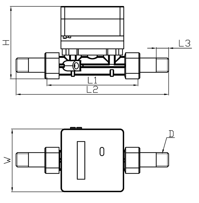
(1) Illustration of DN40 Heat Meter

|
Caliber (mm)
|
Length
L(mm)
|
Width
W(mm)
|
Height
H(mm)
|
Connection type
|
|
DN
|
mm
|
|
|
40
|
200
|
100
|
135
|
R1-1/2
|
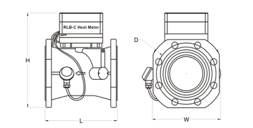
(2)Illustration of Base Meter of DN50-300 Heat Meter

|
Caliber (mm)
|
Length
L(mm)
|
Width
W(mm)
|
Height
H(mm)
|
Connection type
|
|
DN
|
mm
|
|
|
50
|
200
|
150
|
200
|
Flange¢125-4×¢18
|
|
65
|
200
|
170
|
205
|
Flange¢145-4×¢18
|
|
80
|
225
|
195
|
240
|
Flange¢160-8×¢18
|
|
100
|
250
|
220
|
255
|
Flange¢180-8×¢18
|
|
125
|
250
|
230
|
285
|
Flange¢210-8×¢18
|
|
150
|
300
|
270
|
310
|
Flange¢240-8×¢22
|
|
200
|
350
|
320
|
350
|
Flange¢295-8×¢22
|
|
Flange¢295-12×¢22
|
|
250
|
450
|
405
|
450
|
Flange¢355-12×¢26
|
|
300
|
500
|
460
|
500
|
Flange¢410-12×¢26
|
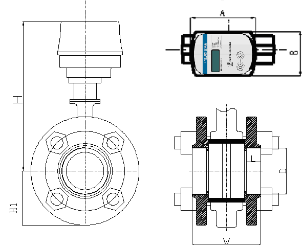
(3)Dimension of DN40 controller

|
DN
|
A
|
B
|
H1
|
H
|
D
|
W
|
L
|
|
40(11/2’’)
|
130
|
161
|
73
|
320
|
1/2
|
100
|
20
|
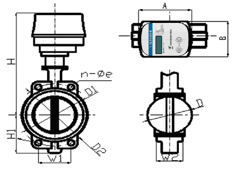
(4)

|
DN
|
A
|
B
|
H1
|
H
|
D
|
D1
|
D2
|
W1
|
W2
|
n
|
e
|
|
50
|
130
|
161
|
80
|
350
|
52.9
|
100
|
120
|
85
|
42
|
4
|
23
|
|
65
|
130
|
161
|
89
|
370
|
64.5
|
110
|
136
|
96
|
45
|
4
|
27
|
|
80
|
130
|
161
|
95
|
376
|
78.8
|
121
|
160
|
61
|
45
|
8
|
18
|
|
100
|
130
|
161
|
114
|
395
|
104
|
156
|
185
|
71
|
52
|
4
|
25
|
|
125
|
130
|
161
|
127
|
415
|
123
|
176
|
215
|
82
|
54.5
|
4
|
23
|
|
150
|
130
|
161
|
139
|
425
|
155
|
212
|
238
|
91
|
56
|
4
|
25
|
|
200
|
130
|
161
|
175
|
435
|
202
|
259
|
295
|
113
|
61
|
4
|
25
|
MAIN TECHINIQUES
1. Alarms when voltage is low.
2. Automatic data correction technology.
3. High definition and wide temperature LCD display.
4. Flow rate has 8 levels and are separately adjusted, with high precision.
5. Ultra-low energy consumption (static power consumption is less than 7μA).
6. The tube adopts forging technology and with straight-through body.
7. Measuring mechanism has no moving parts and no wear and tear forever. The measuring accuracy will not be influenced by using period.
8. Optical interface, long distance communication, can read meter by PDA.
9. Horizontal or vertical installation
10. Automatically upload date to controller at regular time by wireless way.
11. Open and close valve at regular time, which effectively prevent valve rust.
 PRODUCTS