HOW TO USE
1. Remote meter reading
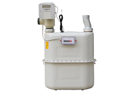
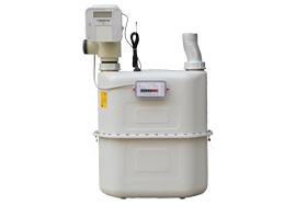
The smart gas meter transmits meter data by wireless meter reading network, the management staff can inquiry gas consumption, valve status, and battery status etc, they can also read meter remotely by wireless meter reading software or hand held unit.
2. Close valve remotely
The gas meter will close valve and stop gas supply after get the command of close valve from the wireless software or hand held unit.
3. Allow to open valve remotely
Transmit command of open valve to the gas meter by wireless software or hand held unit, the gas meter will enter into allow to open valve status after get the command, while not directly open valve.
4. Open valve
When the gas meter in the status of allowing to open valve, press the button on the meter shell, the gas meter will open valve to supply gas (note: press the button cannot open gas meter valve to supply gas if the meter is in the status of forbidden to open valve)
5.
Close valve when attacked
When
the gas meter is attacked by strong electricity and magnet, the meter will
close valve automatically. The attack source should be removed firstly, and
then press the button to open valve and recover gas supply.
6.
Replace battery
The battery need to
be replaced when the gas meter stops gas supply automatically, the
batteries are 3 pieces of AAA alkaline dry battery. When replace battery, open
the battery cover, replace the old battery with new one, and then press the
button on the meter shell to recover gas supply.
FUNCTIONS
1. Micropower technology: the power consumption is less than 10μA at ordinary times, adopt timing detect technique to improve the battery life.
2. Electrical valve technique: adopt electrical valve technique, work reliably and lower loss of pressure.
3. Totally sealed design: all the circuits are sealed by high performance casting glue, so there is no exposed electrode, good leak tightness.
4. Anti-attack of strong electricity or magnet: gas meter will close valve automatically and give indication when being attacked by strong electricity or magnet.
5. Wireless transmission technique: no need of communication cable layout, greatly reduce the installation cost.
6. Micro-computer and microstorage technique: high integrated and high reliability.


TECHINICAL PARAMETERS
|
Item
|
Smart Gas Meter
|
|
Model
|
G6
|
G10
|
G16
|
G25
|
G40
|
G65
|
|
Permanent Flowrate
qn (m³/h)
|
6
|
10
|
16
|
25
|
40
|
65
|
|
Maximum Flowrate
qmax m³/h
|
10
|
16
|
25
|
40
|
65
|
100
|
|
Minimum Flowrate
qmin m³/h
|
0.06
|
0.10
|
0.16
|
0.25
|
0.40
|
0.65
|
|
Transitional Flowrate qt m3/h
|
1.0
|
1.6
|
2.5
|
4.0
|
6.5
|
10.0
|
|
Initiate Flowrate dm³
|
≤5
|
≤8
|
≤8
|
≤13
|
≤20
|
≤32
|
|
Cyclic Volume of
Gas Volume Meter (1) dm³
|
3.5
|
10
|
10
|
20
|
30
|
55
|
|
Weight(kg)
|
5
|
10
|
10
|
18
|
27
|
35
|
|
Total Pressure
Loss
|
≤250Pa
|
≤375Pa
|
≤500Pa
|
|
Minimum Reading
|
0.002m³
|
|
Maximum Reading
|
999999.99m³
|
|
Leak
Tightness
|
No leak when≤45kPa
|
|
Working
Pressure
|
0.5kPa~30kPa
|
|
Basic Error
|
qmin≤q<qt ≤±3%; qt≤q≤qmax ≤±1.5%
|
|
Measurement Accuracy
|
Class 1.5
|
|
Working
Temperature
|
-10℃~40℃
|
|
Security
of IC Card
|
one
card for one meter, cannot be copied
|
|
Life of
IC Card
|
Use
time≥100,000 times
|
|
Alarming
Way
|
Close
valve
|
|
Alarming
Volume
|
The
alarming volume will be 1/16 m³ of the
current purchased volume (count the Integer) or 20m³,
50m³ ( Purchasing volume for one time>255 m³, the alarming volume will be 50 m³)
|
|
Static Working
Current
|
≤20.0μA
|
|
Working Power Supply
|
AA
alkaline dry battery (4 pieces of 1.5V)
|
INSTALLATION
1. The
installation shall be done by the professional person of Gas Power Company, and
shall be installed according to the requirement of code for management of city
gas engineering
2. The gas
meters are forbidden to be installed in the bedroom, bathroom and the place
where there are flammable, explosive and dangerous goods.
3. The gas
meter shall be installed in the good aeration place, and shall be convenient
for reading, observe and overhaul.
4.
The gas meter shall be installed vertically, and cannot slant, and the vertical
missing should be less than 1mm, the horizontal distance between the gas meter
and the gas stove shall not less than 300mm
5.
Power socket and wire can not be installed near the gas line, and the distance between
the power socket and the gas meter shall not be less than 300mm. No power wire
and electrical equipment can be installed 500mm within the gas meter.
6.
Pay attention to the direction of gas meter inlet and outlet, and choose the
right gas meter, as it cannot be installed reversely.
7.
Screw thread is forbidden to be filled with any sealing objects.
8.
After finish the installation, should test the leak tightness. And if it is qualified,
then it can be used. Before inflaming, should discharge all of the air inside
the gas meter and pipeline.
DIMENSION

MAIN TECHNIQUES
1. Micropower technology: the power consumption is less than 10μA at ordinary times, adopt timing detect technique to improve the battery life.
2. Electrical valve technique: adopt electrical valve technique, work reliably and lower loss of pressure.
3. Totally sealed design: all the circuits are sealed by high performance casting glue, so there is no exposed electrode, good leak tightness.
4. Anti-attack of strong electricity or magnet: gas meter will close valve automatically and give indication when being attacked by strong electricity or magnet.
5. Wireless transmission technique: no need of communication cable layout, greatly reduce the installation cost.
6. Micro-computer and microstorage technique: high integrated and high reliability.
 PRODUCTS