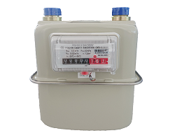
HOW TO USE
The gas meter uses the pressure difference during the flow of gas in
the body of the meter as power, and the relative positions of the valve seat
and the valve bonnet to control the distribution of the gas flow. The capsule
consists of two gas measuring chambers that are identical to each other. Each
gas measuring chamber is divided into two identical small measuring chambers by
a soft membrane. When the distributed gas enters into four small measuring
chambers and pushes the diaphragm to swing freely, the movement of the
diaphragm assembly drives the connecting rod mechanism (double crank rocker
mechanism) through the rocker and causes the valve bonnet to perform rotational
movement so as to control the inflating of the measuring chambers in sequence.
With the exhaust gas, the gas meter continuously circulates, and at the same
time, the crank gear of the link mechanism is driven to count by the gear drive
mechanical counter, and finally the gas meter exhaust amount is displayed
through the counter.
FUNCTIONS
The gas meter consists
of an independent measuring group, a protection shell and a mechanical counter:
1. The independent
measuring group consists of a diaphragm capsule, a high-quality diaphragm, gas
contribution system and drive system.
2. The drive system adopts
single-rotary distribution valve to reduce rotary parts, minimize pressure loss
and enhance reliability.
3. The mechanical counter
cooperates with the independent measuring group with the anti-reverse device,
which can effectively prevent the gas meter counter reading from decreasing
when the gas meter reverses gas transmission.


TECHNICAL PARAMETERS
|
Item
|
Gas Meter
|
|
Model
|
G1.6
|
G2.5
|
G4.0
|
|
Nominal Flow Rate
|
1.6 m³/h
|
2.5 m³/h
|
4.0 m³/h
|
|
Maximum Flow Rate(qmax)
|
2.5 m³/h
|
4 m³/h
|
6 m³/h
|
|
Minimum Flow Rate(qmin)
|
0.016 m³/h
|
0.025 m³/h
|
0.04 m³/h
|
|
Transitional Flow Rate (qt)
|
0.25 m³/h
|
0.4 m³/h
|
0.6 m³/h
|
|
Total Pressure Loss
|
≤200 Pa
|
|
Cyclic Volume(1)
|
1.2 dm³
|
|
Minimum Reading
|
0.2 dm³
|
|
Maximum Reading
|
99999.9998 m³
|
|
Accuracy Level
|
Class 1.5
|
|
Basic Error
|
qmin≤q<qt:≤±3%;qt≤q≤qmax:≤±1.5%
|
|
Working Temperature
|
-10℃~+40℃
|
|
Working Pressure
|
0.5~50kPa
|
|
Explosive-proof Grade
|
Ex ib IIB T3 Gb
|
Note(1): Cyclic Volume means the gas volume that is released by the gas meter
after the gas meter finishes one working cycle.
INSTALLATION
1. The pipe should be cleaned of metal particles,
dust and water before installing the gas meter.
2. The gas meter cannot be installed in bedroom,
bathroom or other area which is sensitive of fire and explosion. It shall be at
least 1.5 meters away from fire. The meter shall be installed in areas which
are waterproof, moisture-proof and avoid long exposure to the sunshine.
3. The gas meter shall be installed vertically and
connected according to the arrow mark on the shell. The moment applied to the
connection during installation shall not exceed 80N·m.
4. A valve to block the incoming gas flow shall be
installed at the incoming connection of the meter. Air-tightness shall be
checked after installation, and the check cannot be performed with fire around.
Incoming pressure of the meter shall not exceed the prescript maximum pressure.
5. To use the gas meter, the outlet valve shall be
opened first, then the inlet valve can be opened to avoid rapid increase of
pressure to damage the construction of the meter. The flow rate of the meter
during use cannot exceed maximum flow rate. This gas meter cannot be used to
measure oxygen and acetylene.
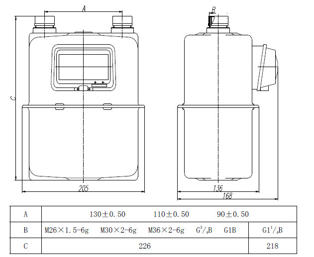
DIMENSION

MAIN TECHNIQUES
1.The diaphragm capsule is molded with anti-gas
corrosion engineering plastic;
2.The diaphragm is made of high-quality polyester
fiber with double-face gluing and a vulcanization process and it won’t
perforate even after 3 million times of test in a deflection test;
3.The valve seat and valve bonnet are made
thorough mold pressing with phenolic thermal solidifying plastics, and are
anti-abrasive, stable and have a low water absorption and low friction coefficient;
4.The protection shell is made of high-quality
deep-drawing cold-rolled steel sheet. The surface is sprayed with a pure
polyester resin (weather-resistant) thermosetting powder coating to increase its
anti-corrosion performance.
5.The transmission between the independent
measuring group and the counter uses a stainless steel shaft output shaft drive
or a stainless steel bushing isolated magnetically coupled drive.
6.The transmission between measuring group and
connector is supported by riveting or electric resistance welding.
 PRODUCTS